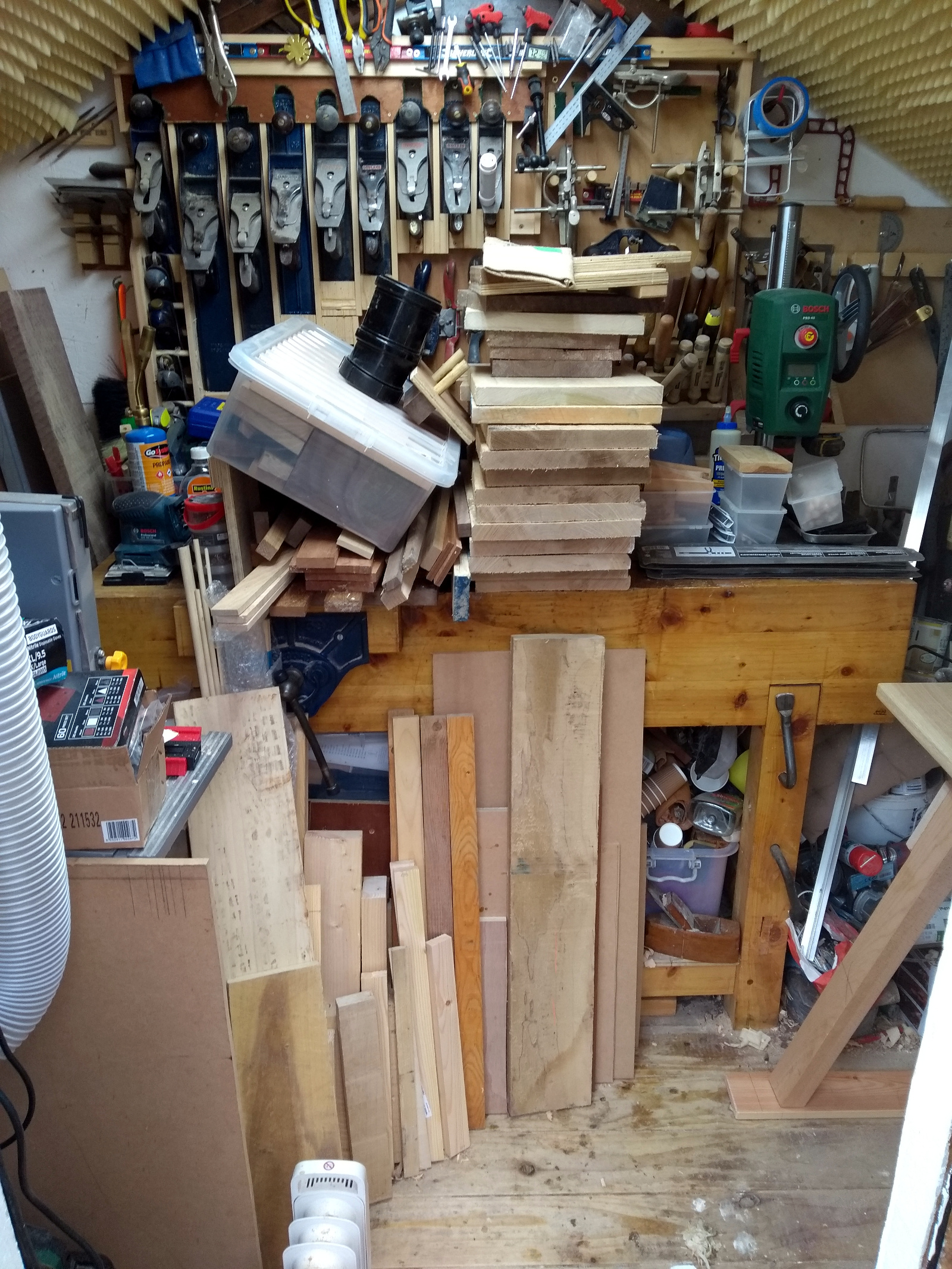
So I kept looking at this and trying to think of where I could stash timber and I kept coming back to the litre-in-a-pint-pot nature of the problem. And some problems you just can’t fix with tidying up stints.
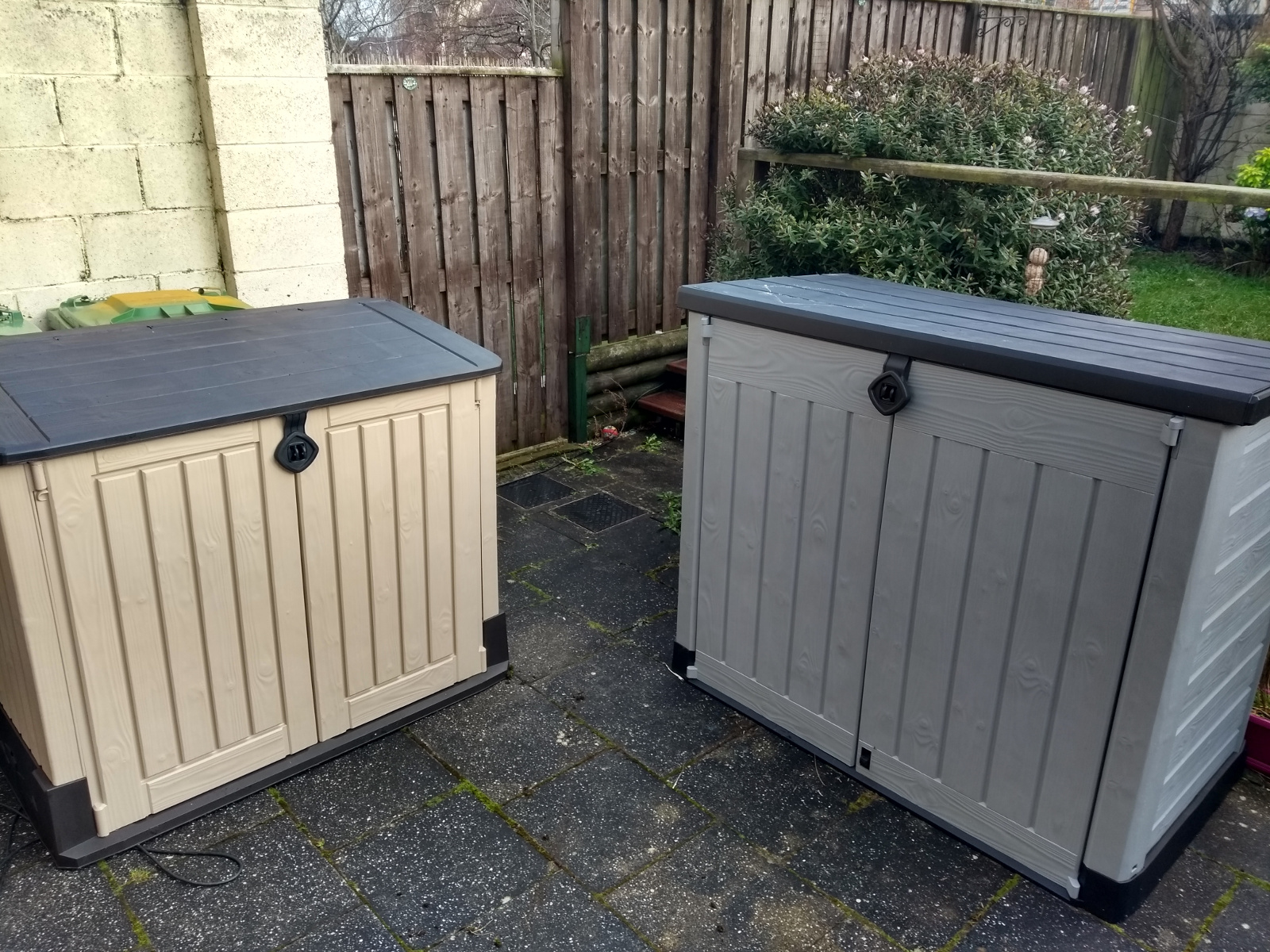
But there’s this little trick you learn in engineering – you can throw money at some problems and they just go away. So I pootled off to homebase and bought a garden storage box (a Keter store-it-out midi for €120 if you’re wondering). And also got the next size up for the garden furniture because it’s driving Claire batty seeing the stuff making the back patio look messy.
Fiddly things to assemble if you get the order of operations wrong and it doesn’t help when your manual is paper mache because someone stored them outside in the rain at the garden center…
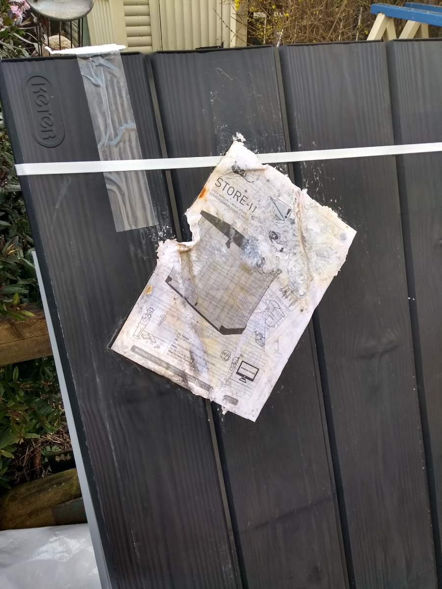
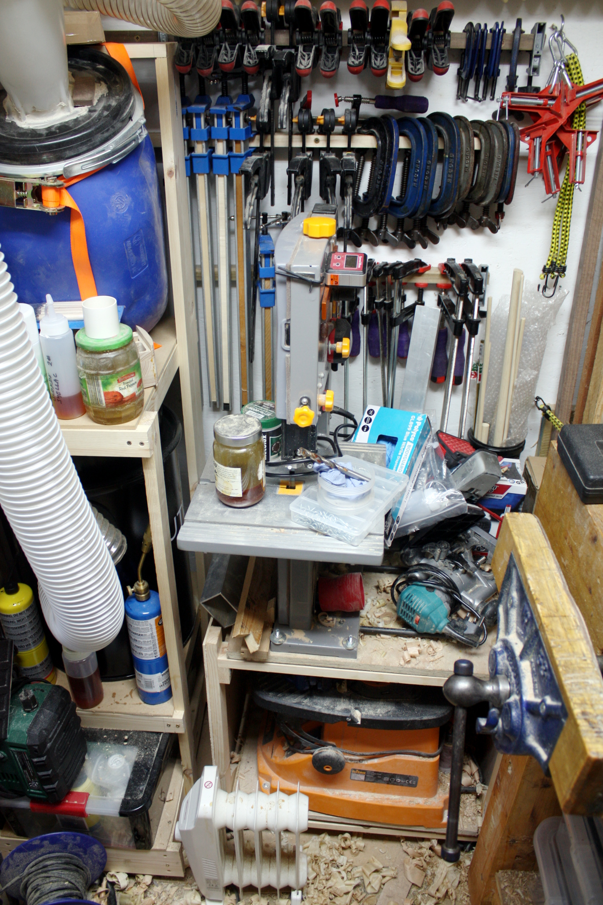
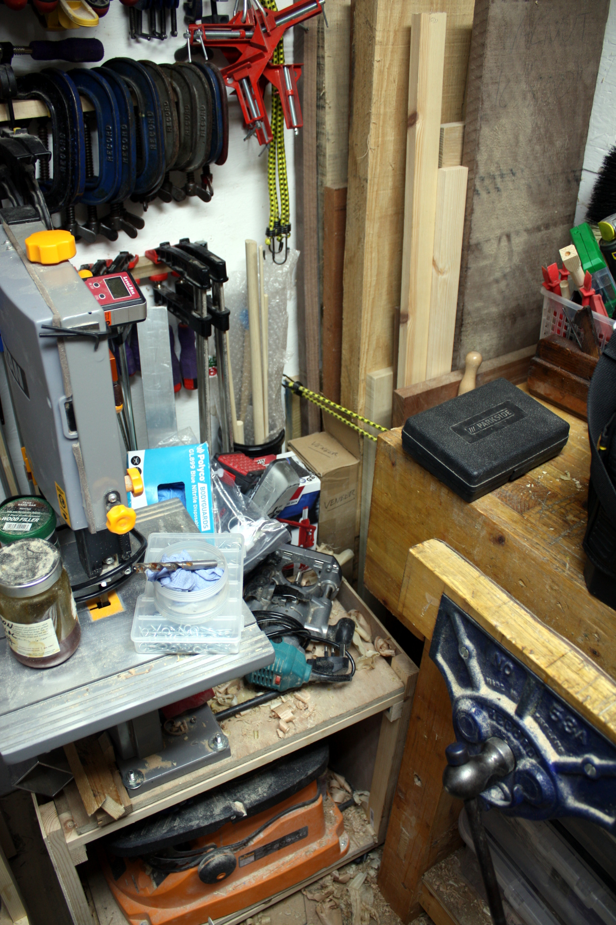
Never seen that before. But thanks to online copies of manuals I got them assembled, and spent most of Sunday moving the smaller one onto that little bit of deck outside the shed and then moving all the timber that would fit into the box and tidying stuff up. The difference is… well, pretty noticable when you’re in the shed.
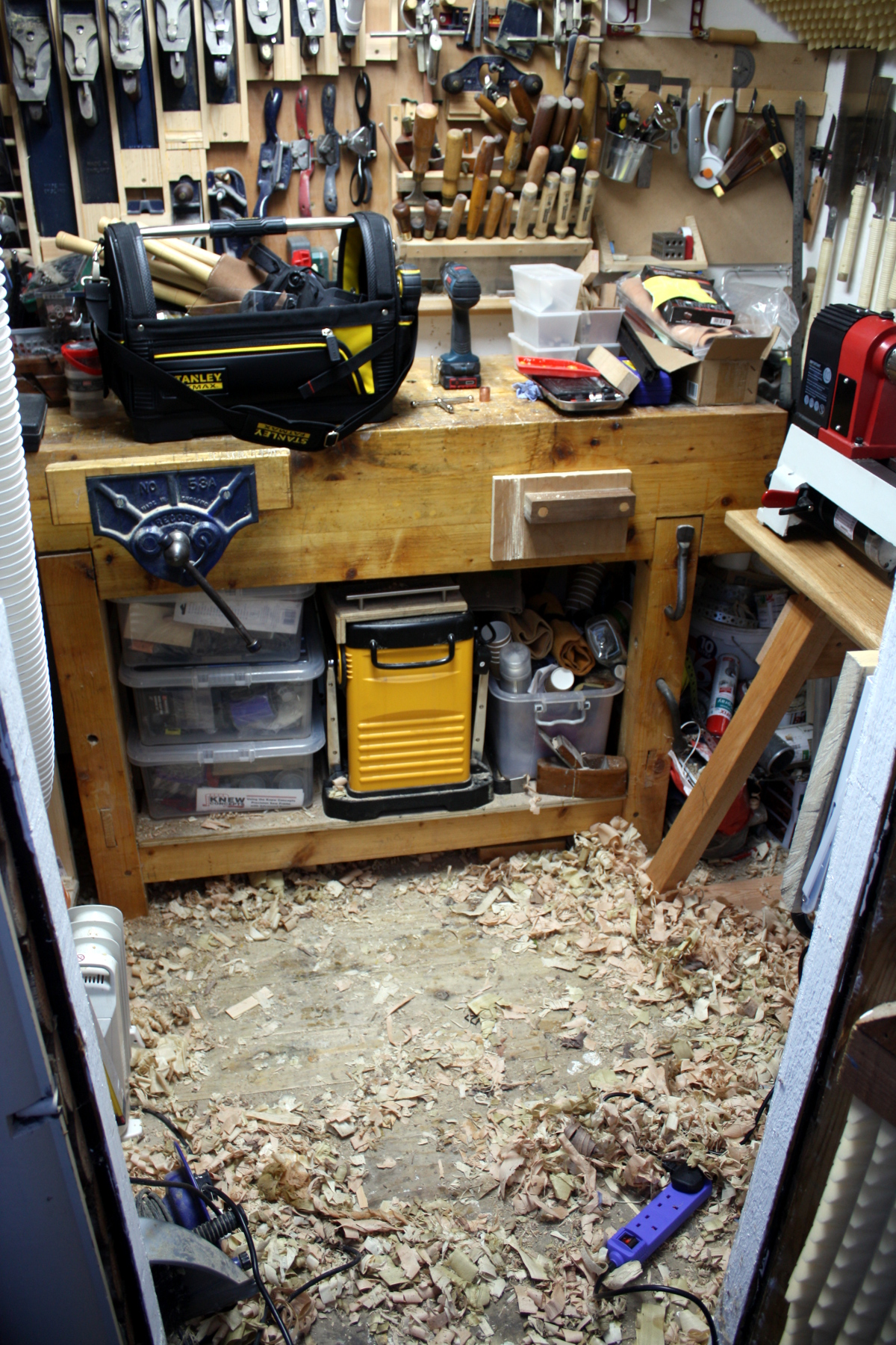
Not done yet, but good grief. I was able to push the bandsaw six full inches to the wall, and I now have enough room in there to actually move around, it’s awesome. I want to put a shelf in the storage box and try to move some of the finishes from the right side of the bench, but that’ll wait for another day.
Oh, and I drilled another doghole in the apron so I’d have a place to put that bench hook for my japanese saws. Works well, wish I’d done it sooner.
The benchtop’s still cramped, but at least now the problem is manageable.
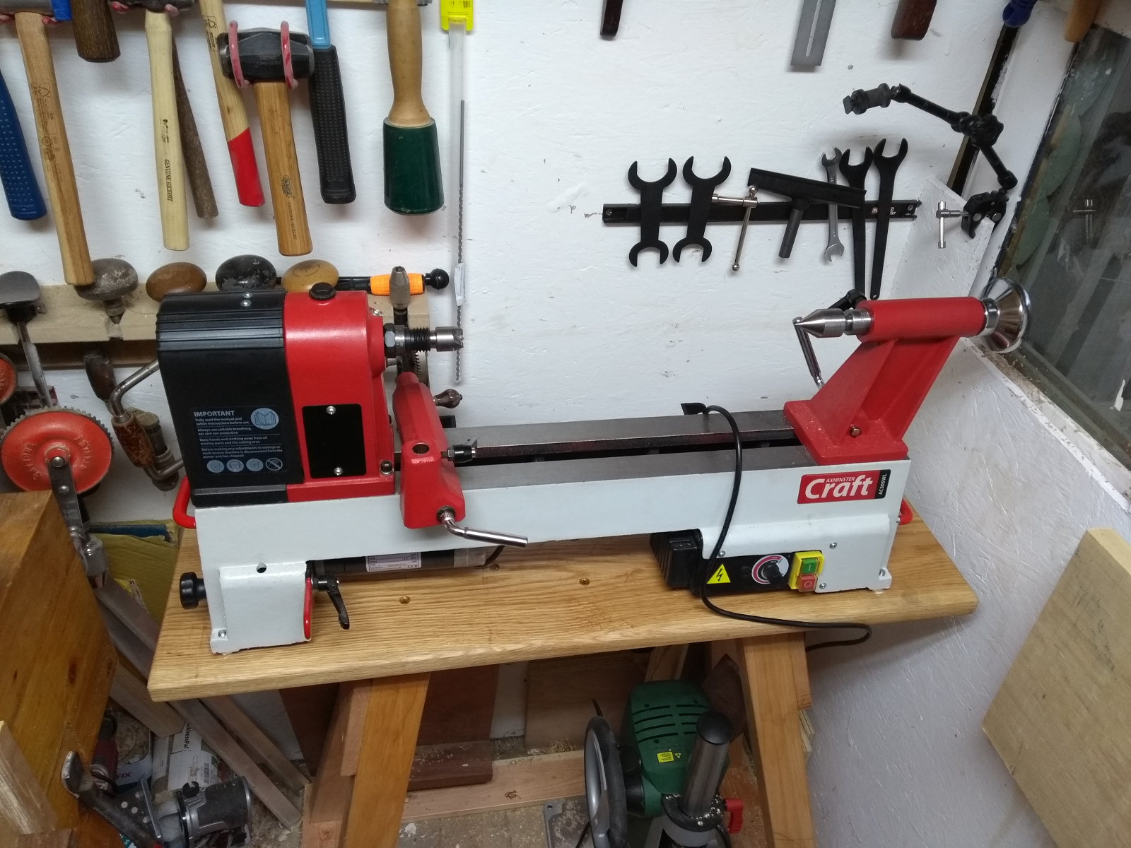
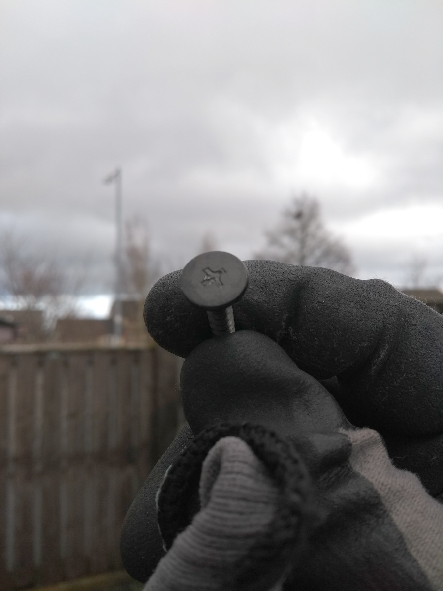
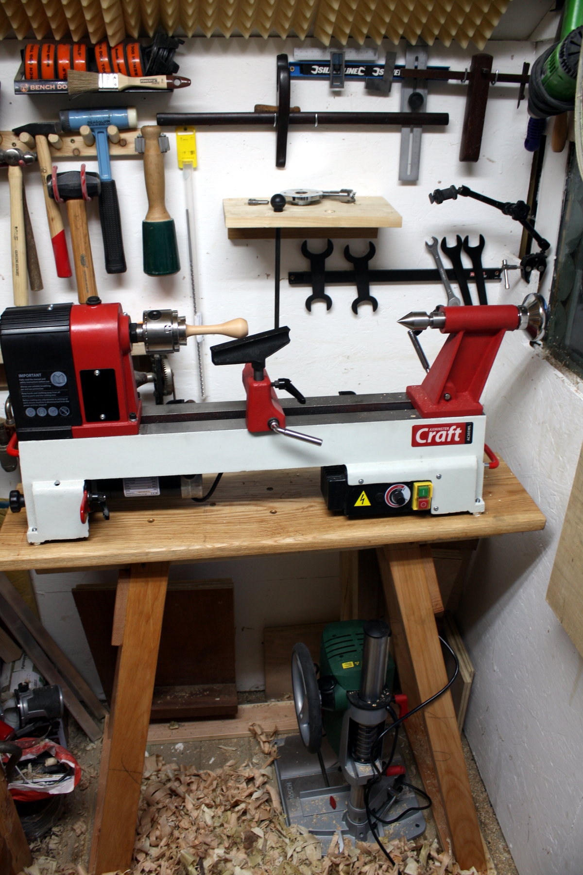
Bolted down the lathe. That was a pig of a job. Turns out, the electronics box (the bit with the switch on the right) hangs *below* the lowest level of the casting when you take off the rubber feet that come with it, so you can’t just bolt the casting down to the stand, you need a spacer (I used M10 nuts for now, but I’ve ordered four ice hockey pucks that I’ll replace the nuts with for vibration damping). And the threading in the casting got painted over so I had to run an M8 tap up through the holes to clean then up, but I had to do that while the lathe was more or less in that position, just swung out a little over the edge to get some access.
And then a misalignment from earlier bit me. When I glued on the top on the stand, I bumped the top at the tailstock end while trying to do the glue-up on the headstock end and didn’t notice (there are downsides to not having any space in the working area beyond inconvenience and safety y’know, the work suffers too):
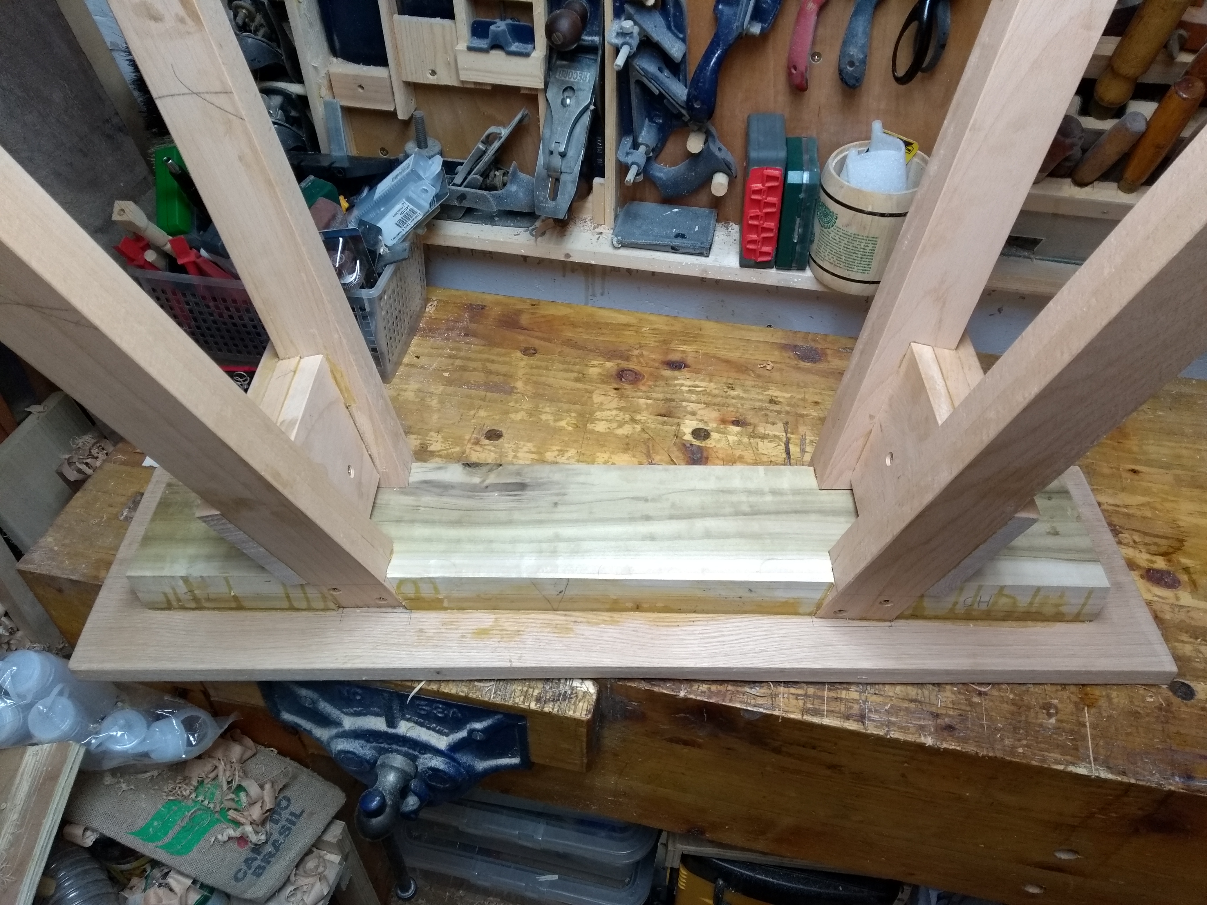
Out by a full 15mm or so. Which means that the bolt through the top from underneath into the casting is fine on one side of the tailstock and on the other side would require me to cut away a chunk of the crossbar to access the nut. *sigh*
I may need to do that (and it’s at the end where the crossbar can lose a little mass anyway) but for now I just threaded the bolt down from above enough to align everything (so the M10 nut spacer doesn’t drift off and leave the casting unsupported) but it’s not holding the lathe down (and yes, the vibration is now much more noticable). When the hockey pucks get here, I’ll fix that.
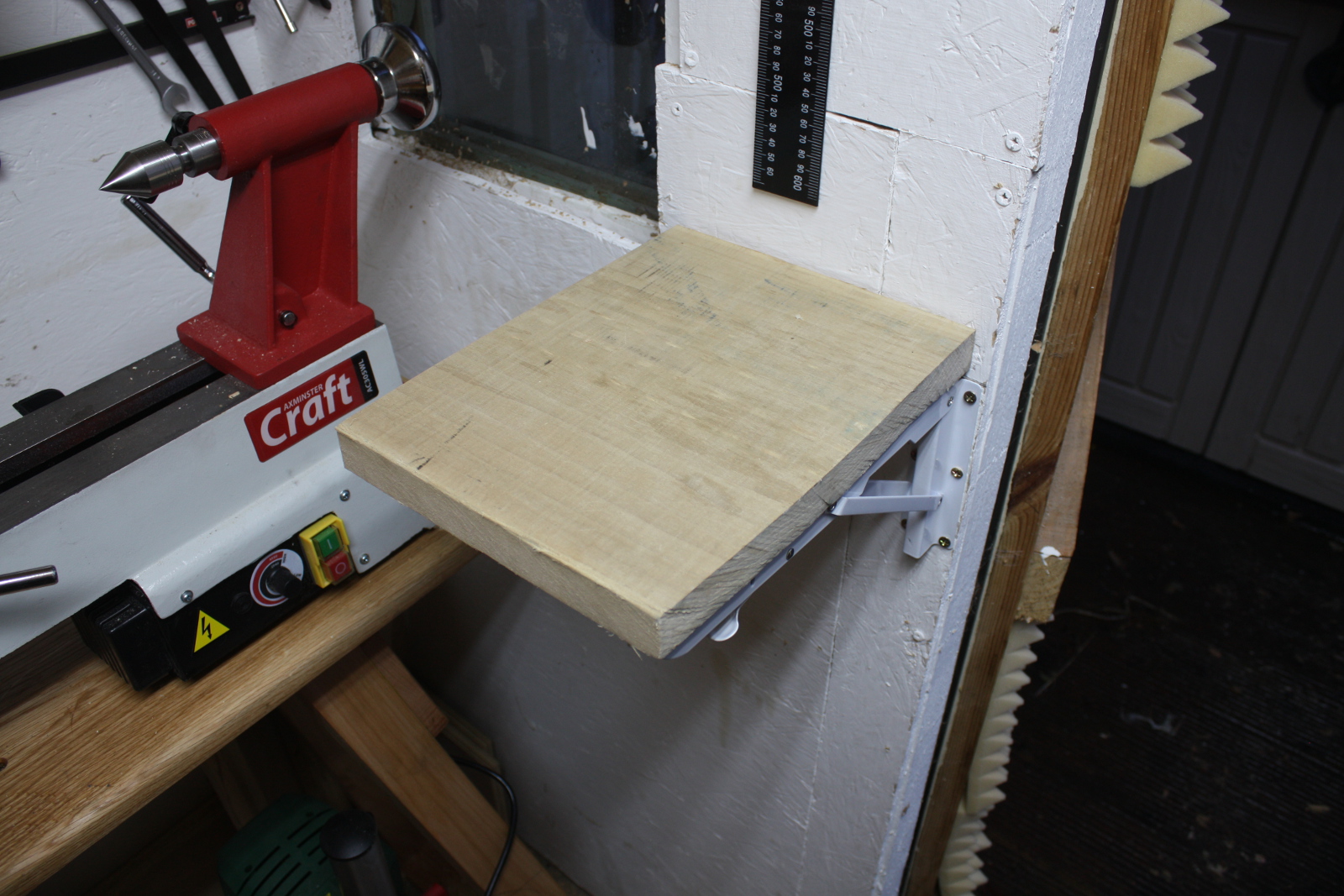
I also put up a really quick and dirty shelf from an offcut.
It has some recesses for the faceplate and the chuck and a hole or three for knockout rod, tool rest and chuck key, but there’s more work to do there, not least of which will be a support from the back to the edge of the shelf as it flexes too much and to move it over slightly to get one of the screws at least into a wall stud (and also more holes for things like the indexing pin for the headstock) But it got more stuff off the bench so that’s fine.
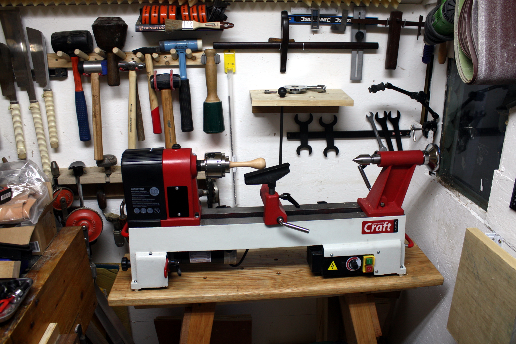
I do have a cheap hall-effect sensor based tachometer to fit as well, which will require removing the electronics box and doing some rewiring and also some mounting holes in the casting to get the sensor close enough to the spindle to sense a magnet mounted on that. The black plastic hood does lever back but the geometry means I can’t just drill into that and mount it that way. Need to think abou this a little.
I also need to figure out lathe tool storage.
Yes, I also need to tidy the shavings, I know, I know. But where do I put the lathe tools is the current question. I don’t like the idea of putting them on the back wall because I don’t want to lean over the lathe; I’m thinking more of a small (2×4) array of pvc pipe segments on the wall below the window and angled towards where I’d stand slightly (I only have six lathe tools, but I want to be able to get one or two more in the next few months). They can’t go by the door which was the natural choice because that’s where the sharpening station is going.
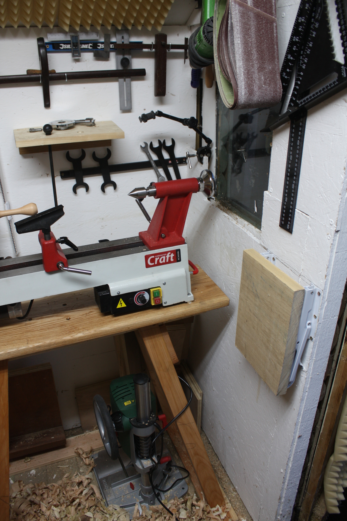
There’s also a little camera arm thingy in there so I can try to get timelapse photos and other fun things later.
And those bench hooks and jigs can’t stay behind the lathe, they fall over instantly when you start the lathe up. Not sure where they’re going. Bit of a pain, those. But waaaay too vital to throw away. They’re nearly daily use tools.
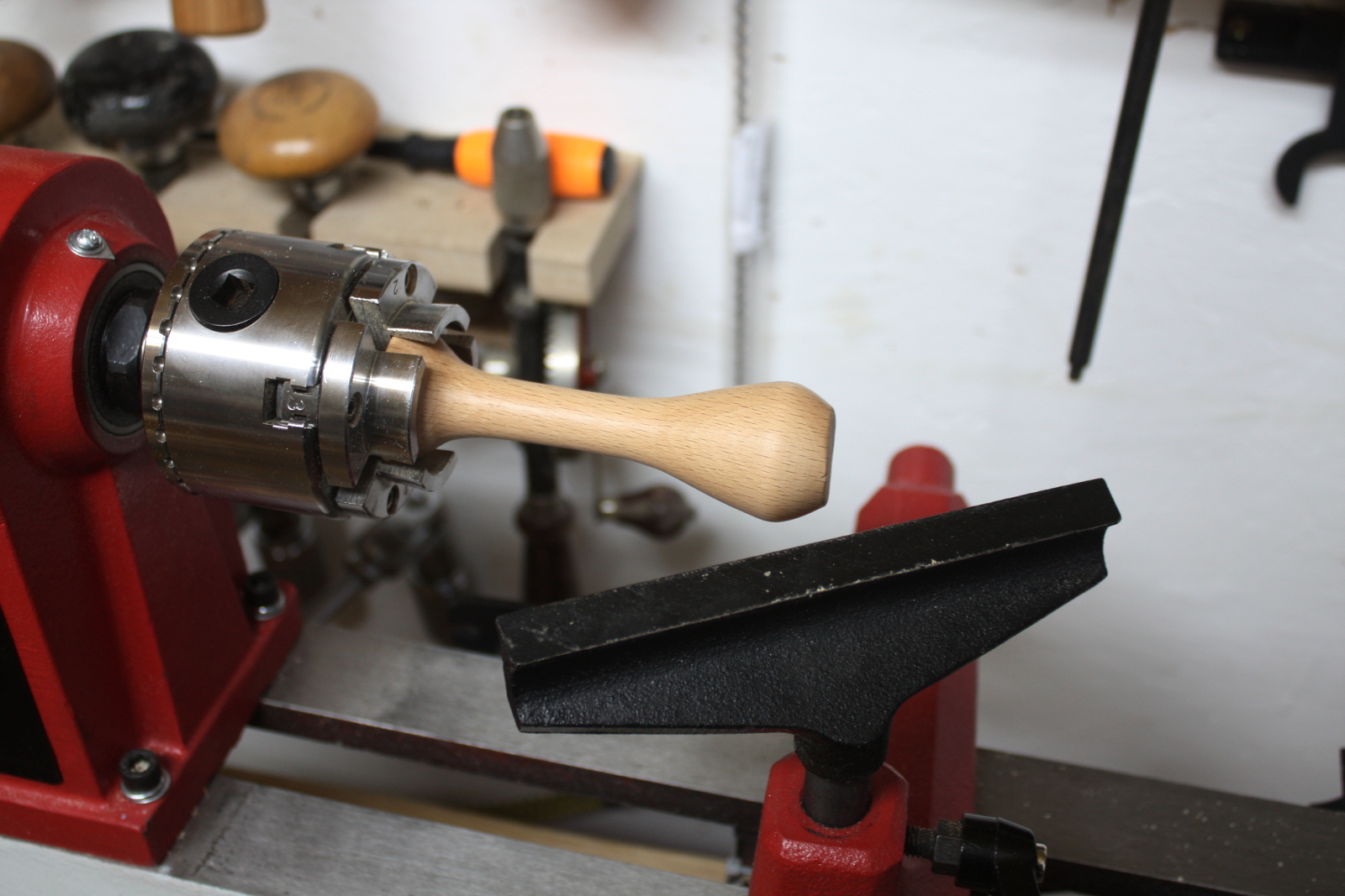
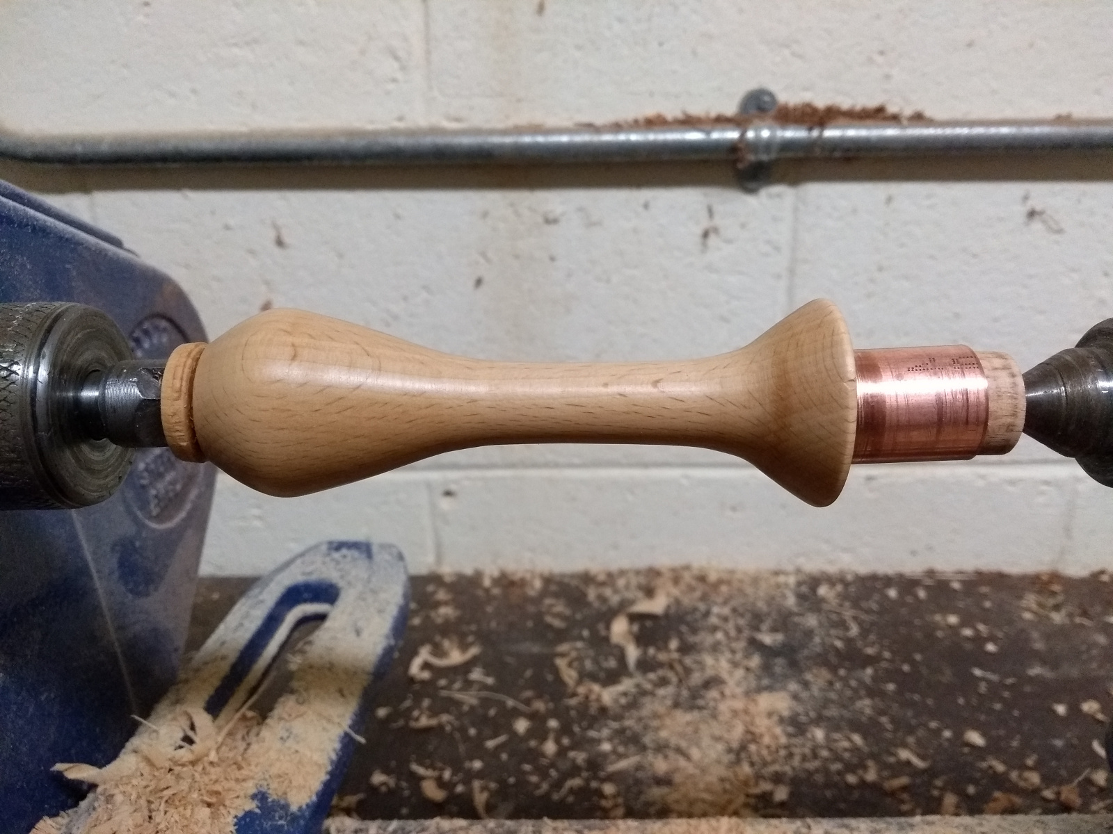
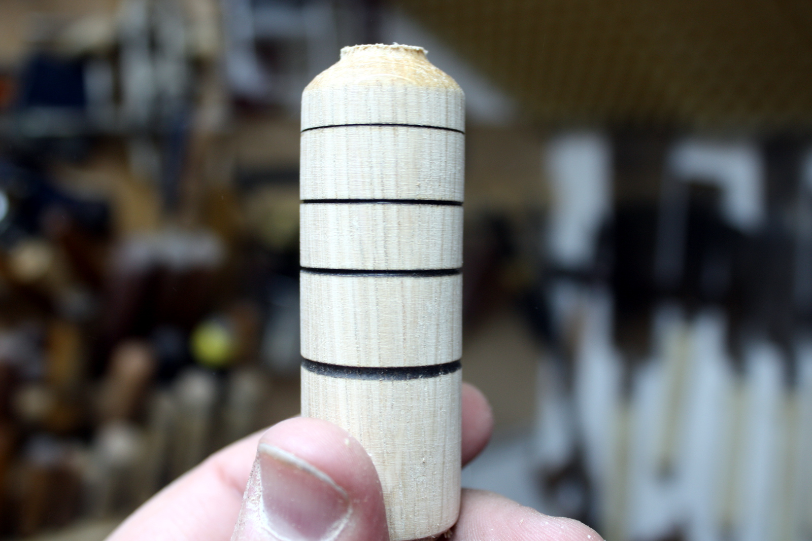
That weird-looking thing in the lathe by the way, is me cleaning up this week’s course project, which was a basic tool handle which is right now holding a saw file. But the bandsaw cut on the back end wasn’t square, and I also had to cut down the ferrule from this:
Still a bit of tidying up to do yet. But at least the long timber is squared away and tied off (and the dowels are in their own 100mm pvc pipe holder).
Need a container for the squeezy bottles of finish and the MMAP and Butane gas though. I might be able to hang those containers off the dust extraction cart if they’re readily removable for when I have to empty that thing. And I have more 100mm hose coming to run the extractor over to the lathe properly, so the sooner I get the 3D printer printing off dust extraction fittings the better. If I can retire the 40mm dust deputy for something like a 100mm Thien cyclone lid for the blue dust barrel, that would work much much better for my little shed as it wouldn’t be banging off the ceiling and I could run the 100m hose to the cyclone instead of the extractor directly.
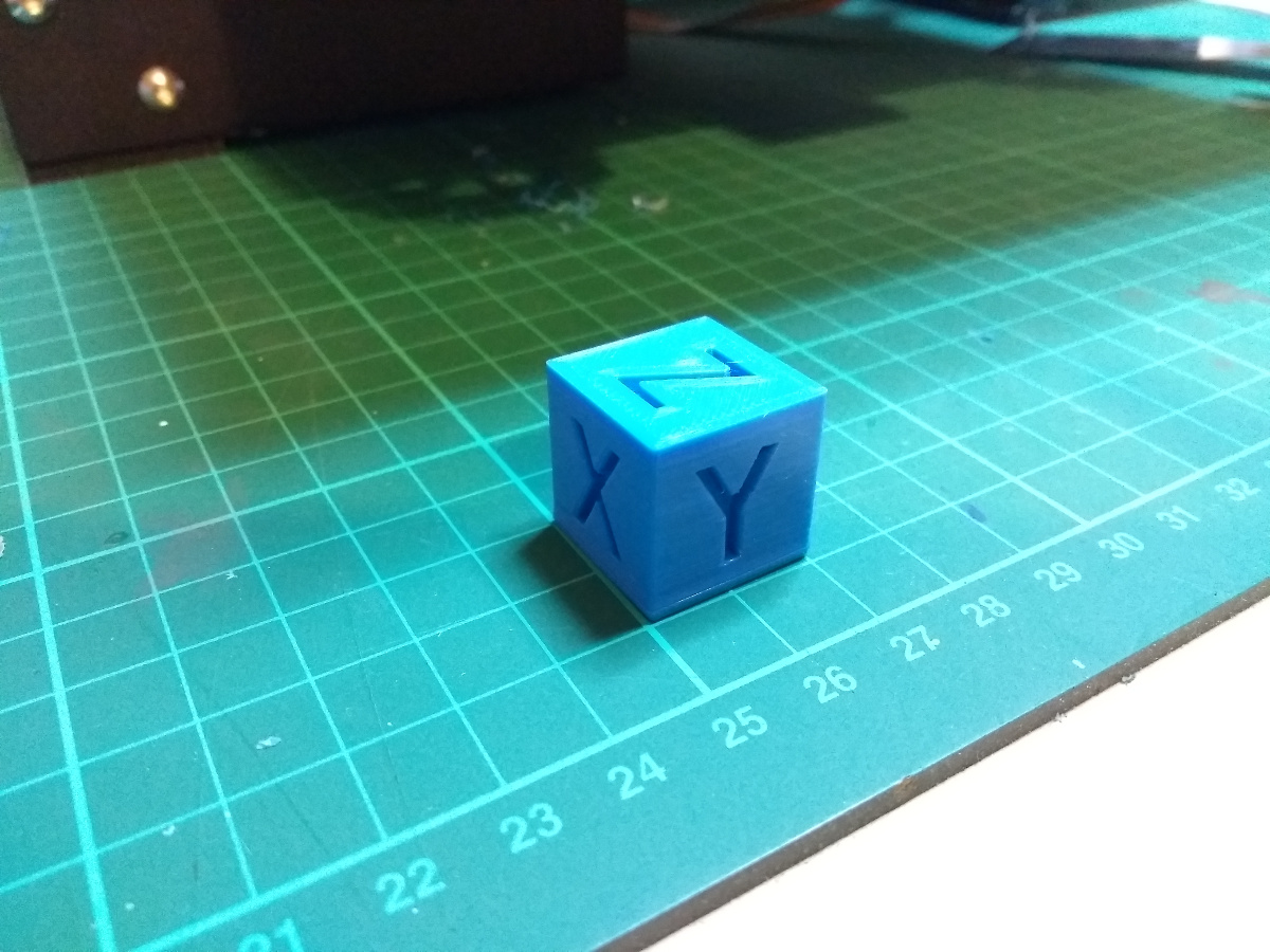
Did manage to get a 20mm calibration cube to print and it seems I’m getting some reasonable results off the printer.
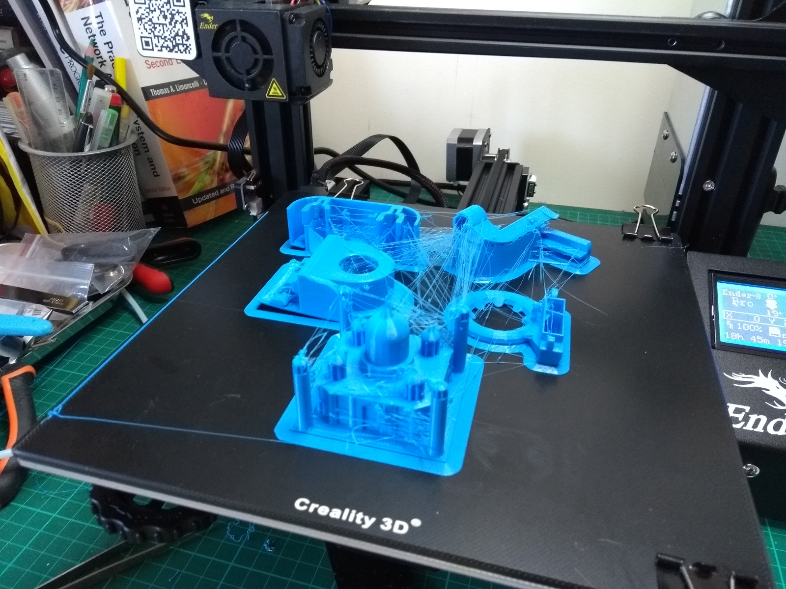
I mean. they’re parts at least. Not a mess of spaghetti behind the machine where the print head knocked it. Yes, that is the Taj Mahal at the front, the rest are parts for the printer itself.
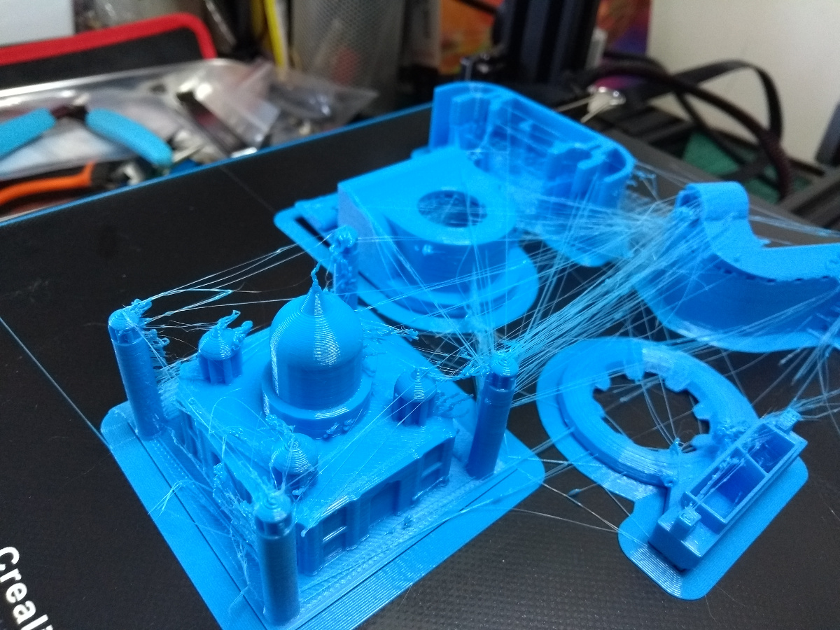
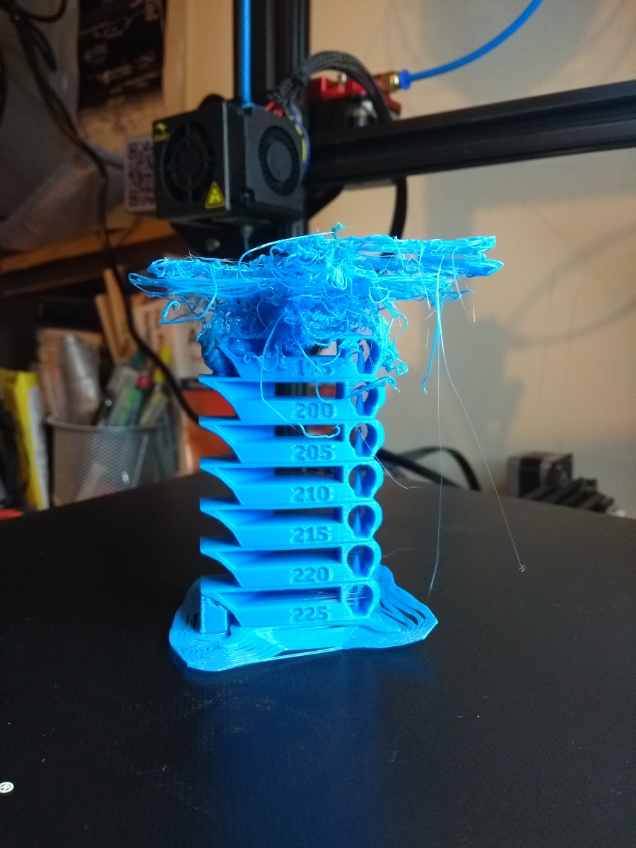
But it does look like spiderman tried to immobilise it (the extruder head needs to come down a few degrees C I think) and for some reason I’m still getting warping but only on the right hand side of the bed?
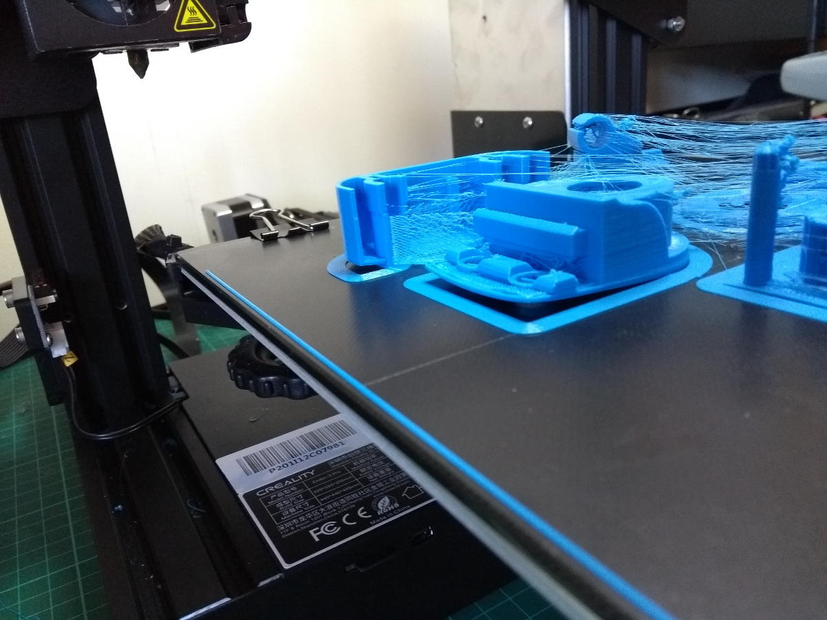
Odd. I’m probably trying to print too many objects at once. Oh well. Prioritisation needed. Parts to improve the printer first, then on to dust collection. I’m running low on filament so I ordered another reel, this time from a manufacturer called eSun instead of this stuff from Creality which has more than a few very loud negative reviews from the various forums for these printers. We’ll see.
Tags: tidying


– “you need a spacer (I used M10 nuts for now”.
I understand bolts are M8, so M8 nuts would allow you fine level adjustment if your stand were warping (assuming bolts tightened from above in the lathe bed.)
The lathe bed is supposed to be more rigid then the lathe bench but…
Now, there is no tool carriage so it is not at all critical on a wood lathe.
– “the sensor close enough to the spindle to sense a magnet mounted on that.”
Two magnets for equilibrium? or, if you don’t want to read twice the speed, at least some counterweight.
Mark,
And I think I have space problems :-). Wood storage is hard, hunks too good to burn but too small to make much can really take up a lot of space.
ken
The problem with an M8 nut is that you need to immobilise the nut while you thread the bolt through and then into the casting Sylvain, you wind up needing three hands throughout the whole process. I’d just shim the lathe stand itself if it wasn’t level (which I had to do at one corner because the floor itself isn’t level), and then screw the lathe to the floor through the shims if it became a problem. It’s a minilathe, it just doesn’t build up enough vibration to be an issue (at least not yet 😀 )
I don’t think I could get away with a metalworking lathe *at all* in the shed, the floor just isn’t up to that level of stress.
Also, mounting two magnets would confuse the tachometer, and you could mount a stronger magnet readily but you’d only gain yourself a few millimeters more range; the sensor just has to be up close. I’ll probably print up a bracket on the 3D printer or make a metal one, and drill and tap the headstock proper to mount the sensor. The position will be awkward – the only space that seems viable is literally underneath the spindle, inside the drive belt. There’s more than enough clearance, but it does just look hairy if the support was to fail through vibration or material fatigue. Proper tapping into the casting and loctite should suffice though.
One of these days Ken I’ll have a bigger shed and then I can laugh at all these workarounds…
…any year now…
…just as soon as property prices in Dublin stop being higher than in Silicon Valley…
Any result yet from the hand washing experiment?
Oh yes!
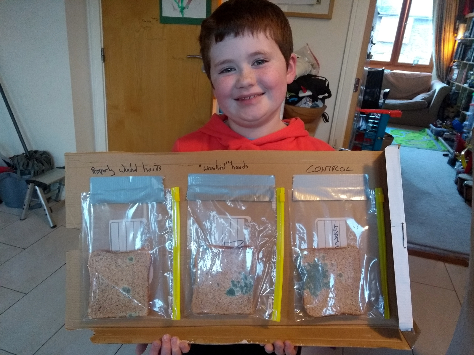
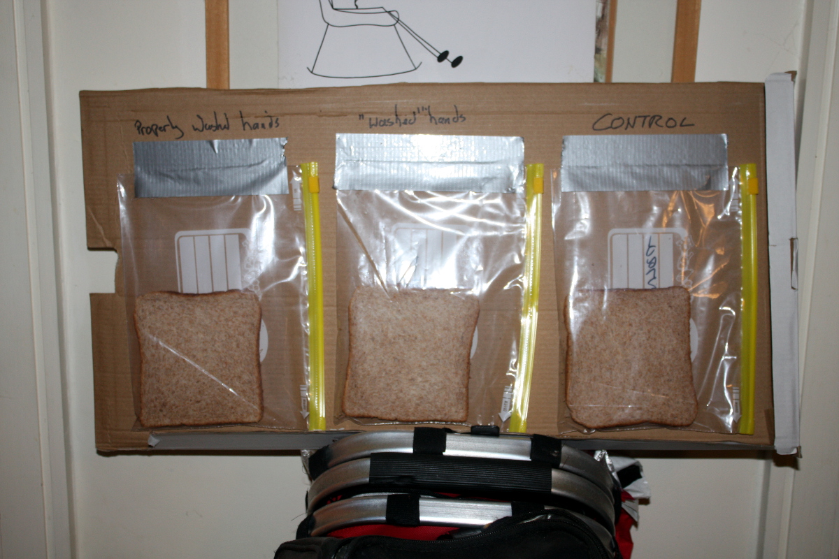
Does it mean the “control” slice was manipulated with unwashed hands and not with gloves?
No, it was handled with tongs taking it from the bag where it would have been placed after slicing by machine. The surface there is lots of small colonies of airborne yeast (which is everywhere worldwide) joining up (which is why it’s so light in colour but so widespread) while the hand-touched colonies are much much deeper and “healthier” which is why they’re single deep-coloured points outcompeting smaller colonies.
Obviously I am no biologist.
I’m not either 😀 I just had time to look up the answer before a seven-year-old asked an awkward question 😉